
A Nike Design That is Just Weird Enough That I Would Love to Give it a Try
Humm, a Nike golf club application with the sole inventor located in Amsterdam, a place known for free thinking. Has “The Oven” moved? The potential jokes are endless, so I will leave it at that.
The following interesting adjustability design is disclosed in a patent application that published last week as US Pub. No. Golf club, golf club shaft and golf club head structures are presented. The golf club may include an adjustable shaft configured to be received in a slot formed in a crown of the golf club head. In some examples, the slot may include a plurality of receivers, such as apertures, configured to receive the shaft in various positions along the length of the slot. The various positions may be progressively closer to a central area of the ball striking surface in order to increase the power transferred to the ball upon striking it.
Check this out!
The application goes on to explain:
[0034] In some conditions, it may be advantageous to provide a golf club head with a shaft that may be adjusted between a conventional position near the heel end of the golf club head and one or more positions located in a more central region of the golf club head. Although much of the power may be generated near the region where the shaft meets the golf club head, the ball may be actually struck in a more central region of the club head. This may reduce the power transferred to the ball upon striking which may cause the ball to lose distance. By joining the shaft to the golf club head in an area closer to the ball striking portion of the golf club, more power may be transferred to the ball during a swing, thereby causing the ball to travel a greater distance.
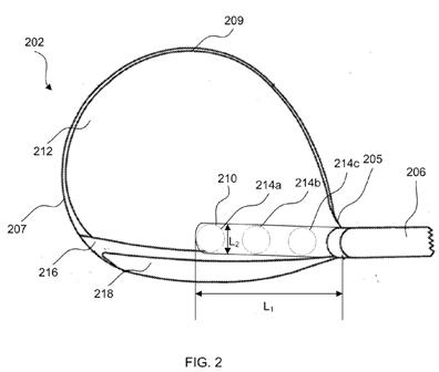
[0035] FIG. 2 illustrates a top view of one example golf club head 202 having an adjustable shaft 206. The golf club head 202 may be any suitable golf club head, such as a wood-type golf club head, and may be formed using any of the methods, arrangements, etc. described above. In addition, the golf club head 202 may include a slot 210 or other recess formed in the crown 212 of the golf club head 202. The slot 210 may be an open slot 210 or may have a lip or edge (as shown in FIG. 4B) to aid in securing the shaft 206 to the golf club head 202. In some examples, the slot 210 may be formed in the golf club head 202 during manufacture of the golf club head, such as during molding or formation of the top or crown of the golf club head 202. In other examples, the slot 210 may be cut into the crown of the golf club head 202 during manufacture or after, as desired.
[0036] In some arrangements, the slot 210 may be formed in the crown 212 of the golf club head 202 and may be positioned vertically above the front face 216 and/or ball striking surface 218 of the golf club head 202. That is, the slot 210 may be formed in the crown 212 and may run along the front face 216 of the golf club head. In some examples, the slot 210 may extend from a heel 205 of the golf club head toward a toe 207 of the golf club head. In some arrangements, the slot 210 may extend from the heel 205 toward the toe 207 and may terminate at a point vertically above and generally proximate to a central portion of the front face 216. In at least one arrangement, the slot 210 may terminate at a point vertically above the center of the front face 216.
[0037] In some examples, the slot 210 may be between 0.5 and 2.0 inches long (e.g., in a first direction along the front face 216 as shown by length L.sub.1) and may be between 0.25 and 1.0 inches wide (e.g., in a second direction extending from the front face 216 toward a rear 209 of the golf club head 202 as shown by length L.sub.2). The slot 210 may be configured to receive the shaft 206, for instance, in one or more receivers, and may be configured to permit adjustment of a position of the shaft 206. For instance, the slot 210 may include a plurality of receivers, such as apertures 214a-214c, into which the shaft 206 may be received. Positioning of the shaft 206 within one of apertures 214a-214c may adjust the position of the shaft 206 with respect to the golf club head 202 and, in particular, the ball striking region 218 of the golf club head. As the shaft 206 is moved closer to a central region (e.g., ball striking region) of the golf club head 202 along the slot 210, more power may be transferred from the golf club to a ball during a golf swing.
[0038] In the arrangement of FIG. 2, the shaft 206 is shown in a first position that may be considered a traditional shaft position arrangement. That is, the shaft 206 is connected to the golf club head 202 near or proximate to a heel 205 of the golf club head 202. This arrangement may place the primary power generated at an area where the shaft 206 meets the golf club head 202 that may be generally offset from the ball striking surface 218 of the golf club head 202. The shaft 206 may be removed from the first position (such as in aperture 214c) and adjusted to another position that may be closer to a central region of the golf club head 202. For instance, the shaft 206 may be inserted into apertures 214b or 214a in order to position the shaft 206 closer to the ball striking surface 218 of the golf club head 202, thereby increasing the power transferred from the golf club to the ball which may increase the distance a ball may be hit. In some examples, the shaft 206 may be slidable along the slot 210 in order to adjust the position of the shaft 206 within the slot 210.
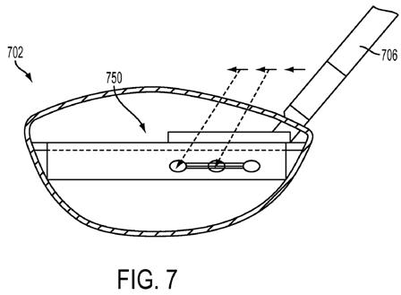
[0039] In some examples, the shaft 206 may include a threaded end which mates with a corresponding thread within the aperture 214a-214c on the golf club head 202 in order to secure the shaft 206 to the golf club head 202. In some examples, a stop may be used to prevent the shaft 206 from completely disconnecting from the golf club head 202. Instead, the stop may maintain a connection between the shaft 206 and, in some examples, the slot 210, to aid in adjustment of the shaft 206 relative to the golf club head 202. In other examples, the shaft 206 may employ another mechanical connector in order to removably secure the shaft 206 to the golf club head 202. For instance, quick disconnect connectors may be used, a button release may be used, etc. In still other examples, a gear type connection may be used. FIG. 7 illustrates one example gear type shaft adjustment system 750 that may be used in accordance with at least some examples of the invention. Similar to the arrangement above, the golf club head 702 may include a slot (similar to the
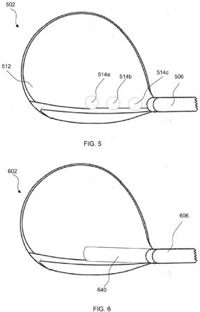
slots described above). A sliding gear system 750 may be contained within the slot and may allow adjustment of the shaft 706 between multiple positions. For instance, the shaft 706 may slide along a gear system 750 and may lock in place in various positions along the golf club head 702.[0040] Although the arrangement of FIG. 2 is described as having a slot 210 with apertures 214 arranged within the slot 210, in some examples, the golf club head 202 may not include a slot 210 and instead may have a plurality of receivers formed directly in the crown of the golf club head that are configured to receive the shaft 206 in various positions along the crown of the golf club head. FIG. 5 illustrates one example arrangement of a golf club head 502 having a plurality of receivers, such as apertures 514a-514c, formed in the crown 512. Similar to the arrangement of FIG. 2, the apertures 514a-514c are configured to receive the shaft 506 in various positions along the top surface 512 of the golf club head 502. In some examples, the shaft 506 and apertures 514a-514c may have a threaded arrangement such that the shaft 506 may be connected to and/or secured to the golf club head 502 via a mating thread in the apertures 514a-514c. Additionally or alternatively, other mechanical or other fasteners may be used to secure the shaft 506 to the golf club head 502 in various positions.
[0041] In some examples, the angle of the shaft relative to the golf club head may remain constant as the shaft moves through various positions along the golf club head. For instance, although the shaft may move or shift closer to a center of the golf club head, the angle of the shaft relative to the golf club head may remain constant or substantially constant throughout the various positions along the golf club head. In other examples, the angle of the shaft relative to the golf club head may also be adjustable via the shaft adjustment system described herein.
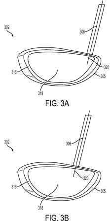
[0042] FIGS. 3A-3C illustrate front views of a golf club head 302 similar to the golf club head 202 of FIG. 2. As shown in FIGS. 3A-3C, the position of the shaft 306 may be adjusted. FIG. 3A illustrates a first position of the shaft 306 connected to the golf club head 302. The shaft 306 is shown in a generally conventional position near the heel end 305 of the golf club head 302. The shaft 306 may include a longitudinal axis (indicated by line 320) extending along the length of the shaft 306. As shown in FIG. 3A, an extension of this longitudinal axis 320 may extend through a portion of the front face 316 near the heel 305 of the golf club head 302. That is, the longitudinal axis 320 generally does not extend through a central, ball striking surface 318 of the golf club head 302.[0043] FIG. 3B illustrates the shaft 306 in a second position within the golf club head 302. This second position is generally closer to a central portion 318 of the front face 316 of the golf club head 302. This arrangement may provide additional power transfer from the golf club to the golf ball during a golf swing because the shaft 306 is positioned closer to the ball striking surface 318. In FIG. 3B, an extension of the longitudinal axis 320 of the shaft 306 may extend through a portion of the front face 316 that is nearer the central, ball striking surface 318. In some examples, the axis 320 may extend through or be aligned with a portion of the ball striking surface 318. For instance, the axis 320 may be aligned with a portion of the ball striking surface 318 that is offset from the center of the ball striking surface 318.
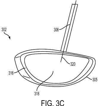
[0044] FIG. 3C illustrates yet another shaft 306 position. This third position is generally closer to a central portion of the front face 316 than the first and second positions shown in FIGS. 3A and 3B, respectively. This arrangement may provide additional power transfer from the golf club to the golf ball during a golf swing by positioning the shaft 306 nearer the ball striking surface 318. In the arrangement of FIG. 3C, an extension of the longitudinal axis 320 would generally extend through or align with the ball striking surface 318 of the golf club head 302. In some examples, the axis 320 may extend through or be aligned with a center or central region of the ball striking surface 318.
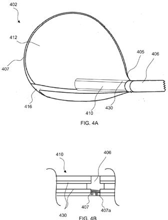
[0045] Although three positions are shown in the shaft 306 arrangements of FIGS. 3A-3C, more or fewer positions may be provided without departing from the invention. For instance, two shaft positions may be available. Alternatively, four, five or more shaft positions may be available.[0046] FIG. 4A illustrates another golf club head having yet another adjustable shaft arrangement. Similar to the arrangements discussed above, the golf club head 402 may include a slot or recess 410. The slot 410 may be formed in a crown 412 of the golf club head and may extend from a heel 405 of the golf club head 402 toward a toe 407 of the golf club head 402. In some examples, the slot 410 may terminate near a central portion of a front face 416 of the golf club head 402.
[0047] The slot 410 may include one or more rails 430 configured to aid in securing the shaft 406 to the golf club head 402. FIG. 4B illustrates a cross sectional view of the slot 410 with the one or more rails 430 visible. In some examples, the shaft 410 may have a threaded end 407 that is configured to mate with corresponding threads in the slot 410. In some examples, a portion of the threaded end 407a may extend into an interior of the golf club head 402.
[0048] In some arrangements, the shaft 406 may be slidably adjustable along the rails 430 within the slot 410. For instance, the shaft 406 may be adjustable through infinite positions along the rails 430. Alternatively, a plurality of stops (not shown) or other finite position markers may be provided to secure the shaft 406 to the golf club head 402.
[0049] In some examples, one or more removable covers may be used to cover at least a portion of the slot formed in the golf club head. FIG. 6 illustrates one example of golf club head 602 having a removable cover 640 covering at least a portion of the slot (not shown). The removable cover may aid in preventing dirt, debris, etc. from entering the slot. In some examples, one or more covers may be provided and may be used with various shaft positions within the slot. The cover 640 may be held in place using known methods of connection, such as mechanical fasteners, snap fits, and the like.
[0050] The adjustable shaft arrangements described above provide a variety of advantages to players. For instance, positioning the shaft nearer the center of the ball striking surface provides power at the primary point of contact, thereby transferring more power to a ball when it is struck which may cause the ball to travel a greater distance. In addition, positioning the shaft nearer the center of the ball striking surface may aid in improved alignment of a players swing with the ball target area of the ball striking surface because the shaft may be aligned with the target area. Further, failure to strike th
e ball in the target area (e.g., in the center of the ball striking surface) may still result in improved power with the shaft nearer the center of the ball striking surface because secondary power regions (such as areas just off the target portion of the ball striking surface) will still receive increased power due to the shaft being nearer the target area.
I can see how a center shafted driver would seem like a good idea (after polishing off a plate of brownies and half a bag of Doritos).
Dave Dawsey – The Golf Lawyer