
A Golf Club Shaft Containing Moveable Weights; Will Nike Golf Bring it to the Market?
I have commented in the past that adjustability of the golf club may be trending away from the golf club head. For instance, recent posts have covered several club manufacturers efforts at developing adjustable shaft stiffness systems (Nike Golf, TaylorMade), adjustable length systems, and even adjustable grips. It was just a matter of time before someone zeroed in on placing moveable weights within the golf club shaft.
Today Nike Golf had a patent application publish as US Pub. No. A device for changing the mass characteristics of a golf club may include a first movable mass. The device may also include a first movable mass guide configured to accommodate longitudinal travel of the first movable mass along the golf club shaft. The first movable mass guide may not extend beyond the distal end of the golf club shaft. The golf club head may include a second movable mass and a second movable mass guide that accommodates travel of the second movable mass.
It goes on to explain:
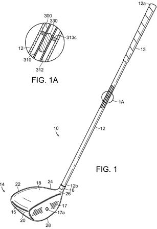
[0067] FIG. 1 schematically illustrates a portion of the golf club shaft 12 cut-away, with an enlarged view showing the details of the cut-away of shaft 12 provided with a movable mass 330. In this particular embodiment, the movable mass 330 is configured to move longitudinally within shaft 12. Additionally, in this particular embodiment, the movable mass 330 is included as part of a movable mass device 300 that is provided within shaft 12. The movable mass device 300 further includes a moveable mass guide 310 configured to guide the movable mass 330 for movement along the length of the shaft 12. In the example embodiment of FIG. 1, the movable mass guide 310 is a slideway formed as a conduit 312 within which the movable mass 330 may travel.
.
.
.
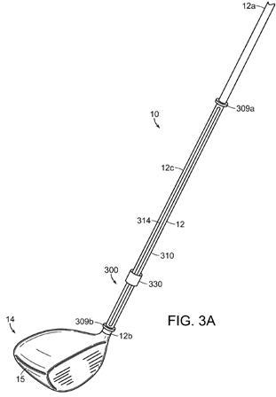
[0069] According to certain aspects, the movable mass 330 may be located entirely within the shaft 12, as shown in FIGS. 1 and 2. According to other aspects, for example, as shown in FIGS. 3A and 3B, a movable mass 330 may be located external to the shaft 12..
.
.
[0076] As even another example, as shown in FIG. 4, the movable mass guide 310 may be formed as one or more flexible, strand-like elements 316, e.g., compliant wires, filaments, cables, etc. The movable mass 330 may slide along the length of the flexible, strand element 316. Referring to another example embodiment as shown in FIG. 4, the movable masses 330a, 330b are slidably located on the strand-like elements 316a, 316b, respectively. In this example embodiment, the strand-like elements 316a, 316b are formed as thick wires extending between two plug-like elements that are secured to the inside walls of the shaft 12. The movable masses 330a, 330b are provided with a central bore through which the strand-like elements 316a, 316b extend. In this example embodiment, any slight lateral motion of the movable masses 330a, 330b may be restrained by the conduits 312a, 312b.
.
.
.
[0079] The physical characteristics of a movable mass guide 310 need not be constant along its length. For example, as shown in FIG. 2, one or more of the ends of the movable mass guide 310 may be enlarged to accommodate a resilient element 308. The resilient element 308 may provide a cushion to slow the movable mass 330 right before and as the movable mass 330 reaches the end of its travel, thereby reducing impact loads and sounds. In one aspect, the resilient element 308 may act as a “soft stop.” The resilient element 308 may be provided as a spring, an elastomeric pad, etc. Further, the resilient element 308 may be shaped to capture or retain movable mass 330. Thus, as shown at the proximal end 12a of the shaft 12, the resilient element 308a may be formed with a relatively soft, foam material having a conically-shaped bore that allows movable mass 330 to become lodged within resilient element 308a. The capture of movable mass 330 by resilient element 308a may be overcome, i.e., movable mass 330 may be released, due to the action of gravity or dynamic forces developed during a downswing. As another example (not shown), the cross-section of the conduit 312 may decrease at one or both of its ends 312a, 312b. The decreasing cross-section at the ends may provide an increased friction force on the movable mass 330, thereby causing the movable mass 330 to slow down and eventually stop. The change in cross-sectional area, if any, may occur abruptly or gradually.
.
.
.
[0081] Alternatively, the movable mass 330 may be a deformable mass. For purposes of this disclosure, a deformable mass 330 may be categorized as either flowable or non-flowable.[0082] In general, a flowable deformable mass 330 has no predefined shape, but rather assumes the shape of the vessel that contains. By way of non-limiting examples, a flowable mass 330 may include non-solids, such as a liquid, a paste, or a gelatin. As another example, a flowable mass 330 may include solids, such as beads or fine particles forming, in the aggregate, a flowable material. Water, with a relatively low-viscosity, may be suitable. Liquid with higher viscosities, such as glycerol or certain oils, may also be suitable. Optionally, as another example, a flowable mass 330 may include a combination of particulates and liquid.
[0083] On the other hand, a non-flowable deformable mass 330 has a predefined shape when no forces are acting on it, but may assume a different shape when subjected to external forces. Referring to FIGS. 8A and 8B, as a non-limiting example, a non-flowable deformable mass 330 may include a flexible external member or skin 331 surrounding a flowable material 332. Thus, as an example, a non-flowable deformable mass 330 could be formed as a liquid-filled elastomeric capsule. As another example, a non-flowable deformable mass 330 could be formed as a gelatin- or paste-filled elastomeric capsule. As even another example, a non-flowable deformable mass 330 may be formed as an elastomeric capsule containing glass or polymeric beads or other material that is flowable in the aggregate. In these examples, the external skin 331 surrounds the flowable material 332 such that the flowable material is contained.
[0084] According to certain aspects, a deformable movable mass 330 may be advantageous. For example, as shown in FIGS. 8A and 8B, a d
eformable movable mass 330e may be provided in a conduit 312e having a constriction 319 (i.e., a reduced inner dimension). The constriction 319, which may be formed integrally with the conduit 312 as shown in FIGS. 8A and 8B, may function as a catch or restraining mechanism. In other words, under certain circumstances, the constriction 319 may restrict the movement of the movable mass 330. The constriction 319 may optionally be formed from an elastomeric material that deforms to allow passage of at least a portion of the movable mass 330 or that provides a gripping force on the movable mass. Under the application of gravity, with the club in any orientation, the deformable movable mass 330e may be wedged or fitted within the conduit 312e at the constriction 319 (see FIG. 8A). However, upon the application of the dynamic centrifugal forces experienced during a downswing, the deformable movable mass 330e may elongate along the line of forces, e.g., in the longitudinal direction `A`. This elongation in the longitudinal direction could be accompanied by a corresponding decrease in the cross section of the deformable movable mass 330e (see FIG. 8B), such that under certain dynamic forces the deformable movable mass 330e could be released to slide within the conduit 312e.
Will this be the next hot adjustability selling point? Can’t you just hear the salesperson saying “the liquid-filled shaft produces too much spin, the paste-filled shaft launches the ball too low, but that gelatin-center is just right!”
Dave Dawsey – The Golf Invention Attorney
PS – click here to read about an adjustable golf ball design